Tetris on Arduino
Interactive LED-Based Tetris Gaming System Using Arduino Mega
Embedded Systems • Game Development • Interactive Electronics
Tetris on Arduino is an open-source educational project. Project circuit diagrams, component links, source code, technical documentation and project images are available through the Open Source Section.
Project Overview
Tetris on Arduino is an interactive LED-based gaming system that brings the classic Tetris experience to physical hardware using an Arduino Mega, a WS2812B addressable LED matrix, joystick controls and an I2C LCD.
The project demonstrates the integration of embedded systems, real-time game-logic programming, addressable LED control and physical user interaction. The Arduino Mega manages the game loop, tetromino movement, collision detection, line clearing, score calculation and display output.

Objective
The objective is to create an engaging and playable Tetris game on physical hardware using an LED matrix display and joystick input for educational and entertainment purposes.
Methodology
Embedded C++
Arduino programming and FastLED are used to control the game engine and LED matrix.
Collision Detection
Algorithms check walls, blocks, movement, rotation, line completion and piece locking.
Real-Time Input
Analog joystick values are processed to provide smooth movement, rotation and drop commands.
Educational Value
This project provides an introduction to embedded-game development and demonstrates frame buffers, game loops, sprite rendering, collision detection, scoring systems, LED mapping and user-input handling on a resource-constrained microcontroller.
Project Specifications
Interactive Game Simulation
Game Statistics
Next Piece
Game Controls
Keyboard: Left/Right arrows to move, Up arrow to rotate, Down arrow to drop slowly, Space for hard drop and P to pause.
Working Principle
The Arduino Mega runs a dedicated game loop responsible for reading joystick input, updating the active tetromino, checking collisions, clearing completed lines, calculating the score and rendering the current game frame on the LED matrix.
The 10×20 WS2812B matrix operates as the physical display buffer. Every logical game pixel is mapped to a physical LED. The I2C LCD presents score and level information, while the buzzer provides sound feedback.
Core Game Loop
- Read joystick input.
- Update the tetromino position.
- Check for collisions.
- Render the frame on the LED matrix.
- Apply the selected game-speed delay.
Tetromino System
I-Piece
Four blocks arranged in a straight line.
■ ■
O-Piece
Four blocks arranged in a 2×2 square.
■ ■ ■
T-Piece
Four blocks arranged in a T-shaped form.
Game Flow Diagram
Hardware Status
Hardware Specifications
| Component | Specification | Quantity | Function |
|---|---|---|---|
| Microcontroller | Arduino Mega 2560 — ATmega2560 | 1 | Game processing and LED control |
| LED Strip | WS2812B 5 V RGB — 200 LEDs | 1 | 10×20 game-display matrix |
| Joystick Module | Dual-axis analog joystick with button | 1 | Player movement and rotation control |
| LCD Display | 16×2 I2C character LCD | 1 | Score and level display |
| Buzzer | 5 V active piezo buzzer | 1 | Sound effects and feedback |
| Power Supply | Regulated 5 V supply rated for the LED load | 1 | LED matrix and system power |
Components Used
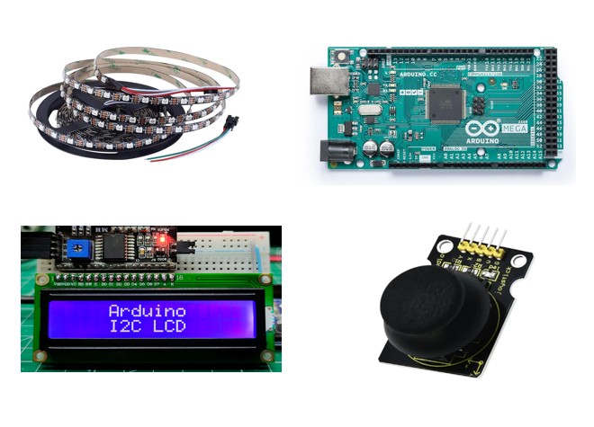
- Arduino Mega 2560
- WS2812B Addressable RGB LED Strip
- 200 Individually Addressable LEDs
- Dual-Axis Analog Joystick Module
- Joystick Push Button
- 16×2 I2C LCD Display
- 5 V Active Piezo Buzzer
- Regulated 5 V Power Supply
- 470 Ω Data-Line Resistor
- 1000 µF Power-Smoothing Capacitor
- Jumper Wires and Connectors
- LED Matrix Frame and Mounting Board
Circuit Design
Circuit Description
The WS2812B strip is arranged in a serpentine pattern to create the 10×20 game matrix. The data input is connected to Arduino digital pin 6 through a 470 Ω resistor.
Wiring Notes
Power-Supply Safety Notice
A WS2812B LED can draw approximately 60 mA at maximum white brightness. Two hundred LEDs could therefore require up to approximately 12 A. Use a properly rated regulated 5 V supply, include suitable power injection and protection, limit brightness in software, avoid powering the complete matrix through the Arduino board, and obtain adult supervision while assembling and testing the power circuit.
Open-Source Project Resources
The project circuit diagrams, component-purchase links, Arduino source code, wiring details, technical documentation and project photographs are available through the Open Source Section.
Conclusion
Tetris on Arduino demonstrates how game-development concepts can be implemented using embedded electronics. The project combines an Arduino Mega, joystick, I2C LCD and WS2812B LED matrix to create an interactive physical gaming platform.
It provides a practical learning experience in microcontroller programming, LED control, input processing, collision detection, score management, circuit design and real-time system operation.
Open-Source Educational Project
Tetris on Arduino is released as an open-source educational project. Its source code, circuit diagrams, component information and supporting documentation may be studied, reused and modified in accordance with the licence and attribution requirements provided in the Open Source Section. Users must retain applicable attribution and should clearly identify any modified versions.