
SURAKSHA
Smart Security Lock with Automatic Attendance System and Automatic Unwanted-Access Stopper System
Security Automation • Embedded Systems • Smart Attendance
SURAKSHA integrates access verification, automatic attendance, door-lock control and unwanted-access prevention in a single embedded platform. Authorised users can be verified through RFID cards or fingerprint authentication, while unauthorised attempts activate a siren, red warning indicator and access-denied response.
Introduction
Conventional door locks normally provide only physical access control and do not automatically record attendance or identify repeated unauthorised attempts. Separate attendance registers also require manual operation and may contain errors.
SURAKSHA was developed to combine electronic locking, user identification, entry and exit monitoring, attendance logging, role-based permissions and unauthorised-access prevention in one system.
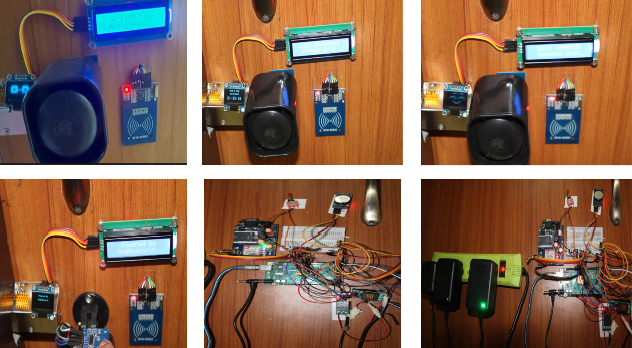
The prototype uses an Arduino Mega as the central controller. RFID and fingerprint systems verify users, while a relay operates the 12 V solenoid lock. The LCD displays access messages, the RTC provides accurate time, and the SD card stores attendance and security events.
Abstract
SURAKSHA is a smart electronic access-control and attendance system developed using an Arduino Mega, RFID reader, fingerprint sensor, I2C LCD, RTC, SD-card module, relay and solenoid lock.
When a user presents an RFID card or fingerprint, the system checks the stored authorisation information. Valid users receive access, the solenoid unlocks and the attendance event is recorded with the date and time.
Invalid, blocked or unauthorised credentials are rejected. The system activates a red indicator and siren and stores the denied-access attempt. A magnetic door sensor monitors whether the door is open or closed, while an exit switch supports controlled movement from inside.
Objectives
Features
Role-Based Access System
Registered User
Can enter using an authorised RFID card or fingerprint. Access may be controlled by working hours, daily limits or account status.
Administrator
Can manage normal access operations, review attendance, resolve access conditions and use selected administrative functions.
Super Administrator
Has unrestricted authorised access, emergency override permission and full system-management capability.
Scientific and Working Principle
RFID authentication works through electromagnetic communication between the RC522 reader and the RFID card or tag. Each registered card contains a unique identification number that is compared with authorised records stored in the program.
Fingerprint authentication analyses the captured fingerprint pattern and compares it with enrolled templates. A matching template confirms the user’s identity.
When access is approved, the Arduino activates the relay and energises the solenoid lock for a selected period. The green indicator turns on, the LCD displays an approval message and the event is recorded with the RTC date and time.
During a denied attempt, the lock remains closed. The red indicator and siren are activated, and the denied event is recorded for later review.
Interactive SURAKSHA Simulation
Select an authentication method and credential type, then press Scan Credential. The virtual lock, attendance counter, LCD, siren, indicators, SD-card logger and door status will update automatically.
Access Test
Security Dashboard
System Outputs
Attendance and Security Log
This browser simulation illustrates the project logic and does not connect to a real lock or attendance database.
Components Used
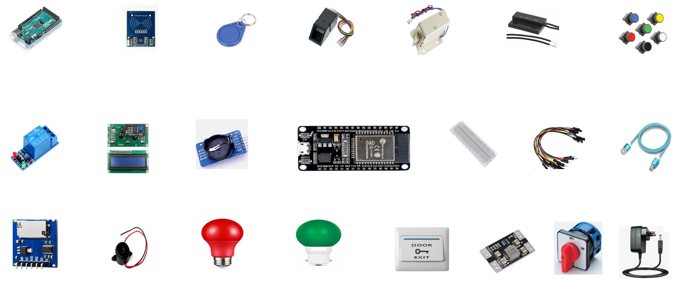
- Arduino Mega 2560
- RC522 RFID Reader
- RFID Cards and Key Tags
- Fingerprint Sensor Module
- 12 V Solenoid Door Lock
- Magnetic Door Reed Sensor
- Exit Push-Button Switch
- Relay-Control Module
- 16×2 I2C LCD Display
- DS3231 Real-Time Clock Module
- SD-Card Data-Logging Module
- ESP32 Development Board
- Emergency Siren
- Active Buzzer
- Red Warning Indicator
- Green Access Indicator
- Breadboard
- Jumper Wires and Connectors
- Step-Down Voltage Converter
- Main Rotary Power Switch
- Regulated Power Adapter
- USB Programming Cable
Technical Description
The Arduino Mega manages authentication, user permissions, attendance records, lock operation and security warnings. RFID card identification is performed using the RC522 reader, while biometric identification is handled by the fingerprint sensor.
The DS3231 RTC provides the date and time used for attendance logging. Entry, exit, denied-access and override events can be stored on an SD card in a structured record.
The relay module controls the higher-current solenoid lock without passing its operating current directly through the Arduino. A separate regulated supply powers the lock and siren.
The magnetic reed sensor detects the actual door condition. This allows the controller to identify whether the door is closed after access or has remained open.
| Component | Function | Role in SURAKSHA |
|---|---|---|
| Arduino Mega 2560 | Main controller | Handles authentication, attendance, access logic and system outputs |
| RC522 RFID Reader | RFID identification | Reads the unique identity of registered cards and tags |
| Fingerprint Sensor | Biometric verification | Matches scanned fingerprints with enrolled templates |
| Relay and Solenoid | Electronic locking | Locks and unlocks the physical door |
| DS3231 RTC | Date and time | Time-stamps attendance and security events |
| SD-Card Module | Local record storage | Saves entry, exit and denied-access data |
| Magnetic Reed Sensor | Door-condition detection | Confirms whether the door is open or closed |
| I2C LCD | User interface | Displays instructions, names, access decisions and warnings |
| ESP32 | Wireless connectivity | Supports future online attendance and monitoring functions |
| Siren and Indicators | Security feedback | Provides immediate visual and audible access-status information |
Circuit and Connection Overview
Authentication and Logging
SPI, I2C and serial communication interfaces are used to connect the authentication and logging modules to the Arduino Mega.
Lock and Security Outputs
The lock and siren use suitable driver or relay stages and an external power supply. They should not be powered directly from an Arduino output pin.
Methodology
- Study security, attendance and unauthorised-access problems in conventional locking systems.
- Select RFID and fingerprint identification for multi-method user authentication.
- Integrate the Arduino Mega, RC522 reader, fingerprint sensor and LCD.
- Register authorised users and define their access roles and limits.
- Connect the relay and solenoid lock and test controlled unlocking.
- Add red and green indicators and a siren for access feedback.
- Integrate the RTC and SD card for time-stamped attendance and security logging.
- Add the magnetic door sensor and internal exit switch.
- Develop entry, exit, daily-limit and administrative override logic.
- Test valid, unknown, blocked and limit-reached credentials under different conditions.
Development Results
The prototype demonstrated RFID-based identification, fingerprint verification, LCD feedback, relay-controlled locking, exit-button operation and visual and audible security responses.
Authorised credentials produced an access-granted response and activated the lock. Unauthorised credentials were rejected and produced an access-denied warning.
The system architecture also supported date-and-time information, attendance-record preparation, door-status detection and administrator override functions.
Project Support and Recognition
DIGITEK Solutions
SURAKSHA received project support and a Research Excellence Certificate for its smart security, automatic attendance and unwanted-access prevention system.
View DIGITEK CertificateFuture Scope
- Develop a secure online dashboard for attendance and security-event monitoring.
- Send instant notifications during repeated denied access or forced-door conditions.
- Add encrypted communication between the controller and online server.
- Integrate camera-based event capture for critical access attempts.
- Add multiple-door and multi-room management.
- Introduce configurable schedules and temporary visitor credentials.
- Provide attendance reports in spreadsheet and PDF formats.
- Add backup power for continued operation during power failure.
- Develop stronger enclosure, tamper detection and weather-resistant installation options.
Proprietary Project — All Rights Reserved
SURAKSHA is not an open-source project. Its design, documentation, source code, access-control logic, attendance system, circuit architecture, user-interface designs, images and technical material may not be copied, reproduced, modified, redistributed, reverse-engineered or used commercially without prior written permission, except where permitted by applicable law.